Accurate Noise Figure measurements on 1296 MHz.It was shown in Part 1 that the receiver sensitivity on 1296 MHz is worth fighting for. The real improvement can be very high. Now let's discuss how to do it in practice.
The first obvious thought that came to my mind is to establish accurate and reliable measurements of the noise figer. For sure it is impossible to improve anything if you can't measure it with sufficient accuracy. The idea is correct of course, but it is not easy to implement it.
TheoryThe main method of measurements of the noise figer is the Y factor method. It is also can be called as "two temperatures" method. The input of the receiver is connected to the matched load and then we measure the output noise level for two load temperatures. Usually it is the ratio of these levels, which is denoted by the letter Y. Let these temperatures be Tc (Tcold) and Th (Thot). The unknown is the receiver noise temperature Trx. Then we have:
Y = (Th + Trx) / (Tc + Trx), hence
Trx = (Th - Y * Tc) / (Y - 1)
We can simply heat up the load and then cool it down but it is too slow for repeated measurements. It is more convenient to add some noise from any noise source in Th position. For example we can get additional noise from a diode in avalanche breakdown. Although the noise in this case is non-thermal nature, it is possible to correlate it with the corresponding noise temperature. This noise is called Tex (excess noise). Then Th = Tc + Tex. In the standard method of measurement we also use base reference temperature To = 290K. The ratio Tex / To is called ENR (exscess noise ratio). This is the main parameter for the standard noise sourse, which is listed in its calibration tables. Typically, noise sourses are of two types, one with a high ENR = 15dB (Tex = 9000K) and other a low level of ENR = 5dB (Tex = 900K).
By simple transformations we can get an equation for the noise factor:
F = ENR / (Y - 1) - Tc / To + 1
If the physical temperature of the noise source is equal to To (290K or 17C), the equation is even simpler:
F = ENR / (Y - 1)
or in decibels:
NF = 10 lg (ENR / (Y - 1))
Now let's define acceptable accuracy. The problem can be divided into two parts. The first is reliable absolute measurement. The second is reliable relative measurement. Absolute measurements are always difficult. It would be nice to get accuracy of about 20%. Relative measurements should to be more accurate. When you tune the LNA it is important to see even small changes in NF. The response to the changes should be clear and with good repeatability. It is desirable that the relative measurements are approximately ten times more accurate than the absolute measurements. Of course now it's only wishful thinking. Let's see what really influences the accuracy. We can find a good analisis of this question in (Noise Figure Measurement Accuracy - The Y-Factor Method, Application Note 57-2, Agilent Technologies ). It was noted that in this Application Note there is an example where the accuracy of measurements is rated as 0.14 dB (10K). This is not really a satisfactory result because when you are measuring a good LNA it can have an error of more than 100%.
Now let's consider the factors influencing on the measurement accuracy. From the begining, I made my life easier by avoiding the problem of measuring the gain of LNA and also the task of measuring NF of the LNA itself (with subtracting of the next stages noise contribution). The gain can be measured by any other known method if required. Only the overall receiver NF is important. Moreover for a properly designed two stage LNA the influence of next stages is negligible.
Now we turn to the main sources of measurement uncertainty.
Uncertainties Linked with the Noise Source Quality:
- Accuracy and stability over time of noise source ENR. As it can be seen from the noise factor equation (above), the ENR calibration error directly adds dB for dB into the NF measurement error . This is the basic problem of absolute measurement as the accuracy of the NF measurements cannot be better than accuracy of the noise source calibration. In Russia the primary standard is held by the State Metrological Centre VNIIFTRI (NIST in the USA, NPL in the UK) and the noise sources on our work benches are not the first copy of the primary standards so the accuracy is limited. In the best case it is 0.1 ... 0.2dB or 7 ... 14K in terms of noise temperature and in amateur practice the situation is surely worse. Of course, for the relative measurements is not so important and the main factor is stability of ENR over the time.
- Noise source VSWR. Accurate analysis of errors related to the mismatch between the output of the noise source and the input of LNA is quite complex, so simplified explanation follows. Part of the noise power entering the LNA is reflected from its input mismatch. Then it goes back and re-reflects from the noise sourse output mismatch. This additive noise sums up with the main noise and introduces an error in the measurement. The error depends on the noise source VSWR and the LNA input VSWR. Of course, it is better to improve the input VSWR of LNA, but it is usually difficult to do so. Good input VSWR of LNA is desirable, but not necessary. It is mostly important for measurement accuracy then for good operation of LNA. We should also remember that the error related to re-reflections depends on the phase of reflection coefficients. I.e. it can be added as well as subtracted from the final result. In one case it can reduce the result; in another it will be improved. The result can easily be misleading and the LNA tuned on a false optimum point. The error due to bad VSWR can be calculated as follows:
δ (dB) = 20lg (1 + ρ 1 * ρ 2)
δ (dB) = 20lg (1 - ρ 1 * ρ 2)
ρ = (VSWR - 1) / (VSWR + 1)
where ρ1 is the reflection coefficient at the noise source output, and ρ2 is the input reflection coefficient of LNA. Both values are calculated and the highest should be taken into account.
However, I prefer to deal with noise temperature, rather than with the noise figer. After transformation we get the error in Kelvin degrees:
δ (K) = 2 Tc * ρ 1 * ρ 2
At room temperature (290K), Tc = To
Let's consider some examples. First we take a poor noise source with VSWR = 1.2 (RL = - 21dB) and the ordinary LNA with an input VSWR = 3.0 Input (RL = - 6dB). In this case NF measurement error is 0.4dB (28K for the noise temperature). Error is 2 to 3 times higher then a good LNA noise figure/ temperature.
Then we take a good noise source, an HP346A for example whose VSWR for 1296 band is better than 1.13. The error will be reduced to 0.27dB (18K), which is still unacceptably high.
The best available noise source on the market is the Agilent N4000, whose VSWR = 1.04. The error is 0.09 dB (6K) which is much better but still not good enough for accurate NF measurements in 0.2dB area. If we want to limit this error to 10%, i.e. 0.02dB, then we need to improve our LNA VSWR up to 1.3 (RL =- 18dB).
Now we see the problem. We do not have sufficient acuracy even for relative measurements. VSWR requirement for an LNA input is too high. In this case we can not surely compare two LNA with medium VSWR and furthermore if we tune any LNA we can easy get false minimum for NF.
- Parasitic modulation of the output impedance of the noise source. This is another problem. It stems from the fact that the impedance of the avalanche noise diode varies greatly during the transition from the "on" state into the "off" state. In order to reduce this effect it is always attenuator installed after the noise diode. The more attenuation we have, the less is the effect of modulation. What is dangerous in modulation? An LNA is usually sensetive to the impedance of a signal source and especially if it is a GASFET LNA. Changing the source impedance leads to a change of LNA gain. This leads to the modulation of the noise at the output of LNA which is not associated with real change in ENR. As a result there is often an error in NF measurements and results in tuning for a false minimum of NF. You can easily get some equivalent of perpetual motion, when the noise figer reaches zero, and even goes into the negative value. This is the reason why 15dB noise sources are not recomended for measuring of NF of sensitive LNAs. To reduce the effect of gain modulation is recomended to use specially produced sources with ENR = 5 dB. In fact they are the same 15dB sources but with additional internal 10 dB attenuator. So the source of ENR = 15 dB can also be used, but with an external attenuator of 10 to 12dB. To save the noise source ENR calibration, the attenuator must be of a good quality with measured attenuation. In details the effect of gain modulation of LNA (Gain Error) was analyzed in the article by Rainer DJ9BV in the early 90s (http://www.mrs.bt.co.uk/dubus/9004-2.pdf ).
- Temperature of noise source. This is an obvious error as the ENR calibration is referred to the base temperature To = 290K. If measurements are taken at other temperature it must be taken into account. In accordance with equation (F = ENR / (Y - 1) - Tc / To + 1), where Tc it is the physical temperature of the noise source. Modern noise sources have a temperature sensor, and the correction is entered automatically.
Errors Mainly Related to Measurement accuracy of Y.
- Error related to the statistical nature of noise. As we know the noise is the result of summation of a great number of independent events. Noise level measurement requires averaging after detection. For better accuracy we need a greater number of independent events which have to be detected and averaged. The number of independent events is proportional to the bandwidth in which we detect noise and proportional to the time. In this case the rule of non-coherent averaging will work. Accuracy is proportional to the square root of the number of events. To double the accuracy we need to expand the bandwidth of four times or to increase the averaging period of time by four. In noise figure analyzers the bandwidth is usualy 4 MHz. This reduces the measurement time and it takes only few seconds to get noise level measurements with an accuracy of about 0.05 dB.
- Error related to non-linearity. This error is related with amplifier non-linearity and with non-linearity of the detector itself. In my case it is within a spectrum analyzer. If we take commerical NF meters, the overall error associated with measurement accuracy of Y is estimated by the manufacturer at the level 0.05 dB.
In all cases it is better to use low ENR noise sources. The linearity will be better if the smaller part of the whole range is used.
Intermediate Conclusions: We have considered all major sources of errors. The findings are generally quite disappointing as even the most precise and the most expensive instruments do not provide sufficient accuracy for measurement in the range of our interest (around 0.15 dB NF). I came across this problem three years ago and started looking for alternative measurement methods. The default method is to use cryogenic load for NF measurements. The problem with an ordinary NF meter is that the noise temperature of modern LNAs reached the level of cryogenic temperatures even without cooling. But we are still forced to do measurements with a hot noise source having a temperature of about 300K. For example, suppose that we want to measure the sensitivity of the LNA with a noise temperature in the region of 15K (NF = 0.21dB), and that we want to do it with an accuracy of 20%. This corresponds to an error of plus or minus 3K. But for measurements made with the room temperature noise source (300K) this 3K error is no longer 20%, it is now only 1% and it requires a super-precision tool.
Noise Measurements with a Cooled Load.Consider for example of using a liquid nitrogen cooled load. This corresponds to a temperature of 78K and we are talking about a decrease in temperature compared with room temperature at about 3.7 times. Consider some of errors described above:
- Noise source VSWR: Error due to mismatch in percentage terms does not change, but in absolute terms decreased in 3.7 times (Tc = To / 3.7). For the same accuracy requirements for matching is markedly reduced.
- Parasitic modulation of the output impedance of noise source: Here is even more improvement. Firstly at the same percentage of parasitic LNA gain modulation error will decrease 3.7 times. Secondly in this case we need 3.7 times less ENR. Additional 3.7 times attenuator will provide greater stabilization of the noise source output impedance.
- The error related with the statistical nature of noise: Error in percentage remains the same, but in absolute terms decreased in 3.7 times. Accordingly for the same accuracy averaging time can be reduced by 13.7 times (3.7 squared).
- Error related to the nonlinearity: here is the same pattern. Error in percentage remains the same, but in absolute terms decreased in 3.7 times.
Conclusion: The use of cooled load is a very effective way to improve the accuracy of measurements of the LNA noise figure.
Practical Realization of the Cold Load.The classic solution is to cool it with liquid nitrogen, but it is not easy to realize. We need a load that work well at the temperature 78K in that it must be insensitive to repeated and very serious thermal cycling from room temperature to the boiling point of liquid nitrogen. The output connector must be at room temperature, and not look like a frozen icicle. The output of the coaxial line usually requires a heater with a thermostat. The coaxial line is also complicated as its parts are heated to different high range temperatures and of course we need to maintain a good VSWR into it. Then the line should have minimal losses, because these losses will generate additional thermal noise and increase the noise temperature of the load. Third, the thermal conductivity of the line should be low to reduce heat loss and eliminate unnecessary heating of cooled load. I have not tried to build this so I have probably not identified some of the other technological problems. But even if you solve all these problems or if you get a commerical cold load there is another problem as you need a source of liquid nitrogen. It is acceptable expence in scientific research laboratories but at home it is a waste of time and money. Unfortunately, without a liquid nitrogen it is difficult to obtain cryogenic temperatures . Peltier elements can lower the temperature only a few tens of degrees. "Dry ice" or solid carbon dioxide (CO2) is only at -79C and this will improve the accuracy of measurements by only one and a half times. There is also a closed-cycle cryocooler, but it is expensive. Of course, liquid nitrogen cooling gives a very important advantage by fixing the temperature of the load to a certain value. It is important for calibration of the measuring load, but here, too, not as simple as it would appear. We know exactly the boiling point of pure liquid nitrogen but practicaly available liquid nitrogen can have a significant percentage of oxygen in its composition, which may change the boiling temperature of the mixture. A second problem is the loss in the coaxial line and connector which as a result will have at the output not 78K, but let's say 85K. Moreover accurate measurement or calculation of this increment is extremely difficult.
Fortunately there is another way to realize a cold load. With the antenna aimed at the cold part of the sky. This is the way I decided to go. We know that the ideal antenna (with only the main lobe and the 100% efficiency) will have on its terminals a noise temperature which is exactly corresponding to the noise temperature of the observed region of the sky. A real antenna is always slightly worse as there are back and side lobes in the pattern and there are also some losses. All this affects the noise temperature. In a city there are also numerous man-made noises, so the requirements for a clean antenna pattern is very high.
The best antenna for such a purpose is a horn. Although even the usual pyramidal horn is considered as a low-noise antenna, with a dual-mode optimized horn the result is much better. I had the good support from Dmitry RA3AQ who was able to calculate the dimentions for a horn with surprisingly clean radiation pattern (Figure 3.1 - 3.2).
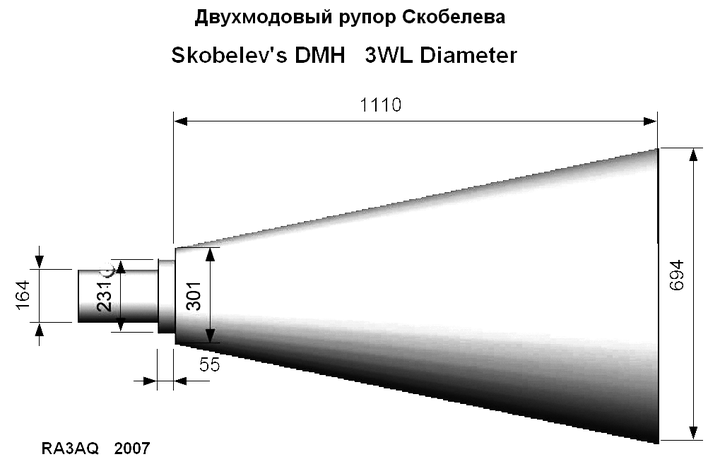 Fig. 3.1
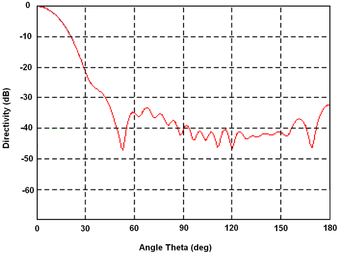 Fig. 3.2
I asked my nephew to help in the manufacture and installation of this horn and the final result is shown mounted on the wall in Figure 3.3.
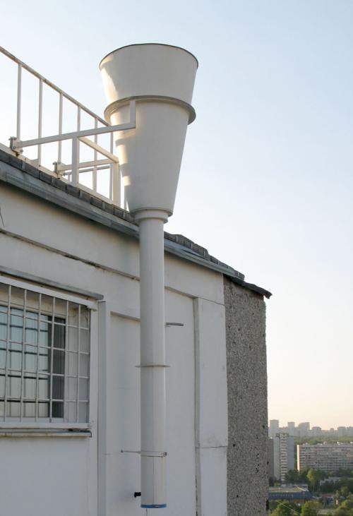 Fig. 3.3
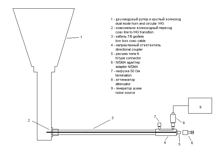 Fig. 3.4
Some details of the design are visible in the pictures Figure 3.5 ... 3.8.
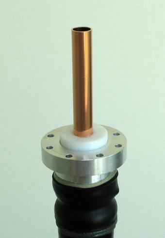 Fig. 3.5
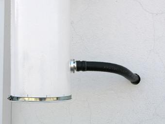 Fig. 3.6
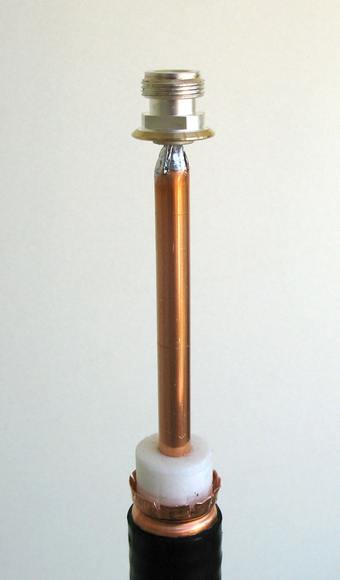 Fig. 3.7
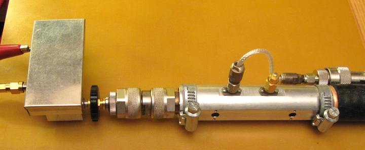 Fig. 3.8
The first measurements were very good but it took some time for further testing and refinements to confirm them. The result was a 14K noise temperature at the output SMA connector when a cold region of the sky was at zenith and no additional interference was received.
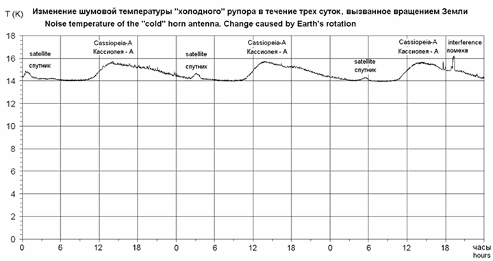 Fig. 3.9
Figure 3.9 shows the change in noise temperature caused by Earth's rotation. The maximum corresponds to the passage in the zenith of the powerful source Cassiopeia-A. The slope is moving along the Milky Way. We also see a speedy and smooth noise increase caused by some satellite with a periodicity of 26 hours. Sharp surges are interference from terrestrial sources. To avoid interference had to change the measurement frequency. Now I measure at a frequency of 1292.5 MHz. However for broad-band LNA, it does not lead to appreciable errors. Daily variation of noise temperature can be avoided when you direct a horn at the North Star. But it is well only for high latitudes QTH. Zenith is the best direction to reduce atmosphere thermal noise and interference.
These problems are minor and easily to adapt to but the main advantage is the very low temperature of noise source where improvement is not 3.7 times as for liquid nitrogen but as much as 20 times. "Cold" horn antenna ensure a very high improvement in measurements accuracy (20 times)! This gives the following advantages: - You can completely forget about the error caused by the noise source impedance modulation (Gain Error).
- With a good VSWR on the measuring connector (say VSWR = 1.05), which is easily achievable in our narrow band, we can also ignore the error associated with a mismatch at the LNA input. For an LNA input VSWR = 3 the error due to mismatch will be only 0.35K (0.005dB).
- Measurements can be achieved 20 times more accurately . At same accuracy we can shorten the measurement time by 400 times. This allows for fast and accurate measurements of the noise figer.
However there is even more advantages. It is possible to tune LNA with real time measurements while connected to a real antenna. After tuning an LNA with a broadband load at the input of LNA (the standard noise source) it often lose stability when connected to a real antenna. In this case we have to ensure redundant stability of LNA but it reduce noise parameters. Repeated checking of the LNA with a real dish antenna is a hard work. My experience shows that if the LNA is stable with measuring horn it will always be stable with a real antenna feed. It is very convenient for tuning.
We were talking still about the relative measurements which are especially important in the of LNA optimization. We have to move with small steps and it is very important not to err in the desired direction. In this sense, the usual measurements at room temperature, are rich with all sorts of false LNA tuning. It is also very important to compare the LNAs with different input VSWRs and it in particular to use one or two "reference" LNAs to calibrate the system. A well made LNA keeps its parameters for a long time. Noise temperature of the horn varies in time and periodic calibration is required and especially if we want to measure thousandths of a dB. So I initially counted on relative measurements and I was hoping to calibrate the system by using an accurately measured LNA. Later I came to the understand that it is unrealistic to find an LNA with a measured accuracy of 1 to 2K. But I also began to unerstanding that absolute measurements with a "cold" horn antenna are quite possible and the accuracy of these measurements may well compete with the accuracy of measurements by using commerical equipment. Let's see how this can be done.
The only absolute measurement available with a good accuracy is a measurement of the ratio of noise levels for the two cases. First, when the input of the LNA is connected to horn antenna Ta. Second, when connected to the load which has a room temperature To. Then we have:
Y = (To + Trx) / (Ta + Trx)
If Y is known, then after transformation we have:
Trx = To / (Y-1) - Ta * Y / (Y-1)
There is no single solution for Trx equation because temperature Ta is also unknown. However we can evaluate the limits for Ta. First of all we need to evaluate lowest and in accordance with the equation that gives the maximum limit for noise temperature of the receiver. If the actual noise temperature of the horn is higher, it will only improve the results of measurements. Therefore, the temperature of the horn will be evaluated on a minimum value.
Let's look at what noise contributions we know almost for sure. We have the cable at 5K, the directional coupler at 0.5K, the output connector and N / SMA adapter at 1.5K, the waveguide 1K, the horn itself and its plastic cover at 0.5K, the noise of the atmosphere at 1.5K and cosmic noise 4K for a total of 14K. The loss data for the cable is taken from the datasheet and confirmed by my own measurements on large pieces of cable. The cosmic noise and atmosphere noise data comes from reliable sources. The directional coupler noise is the room temperature of noise source divided by the coupling factor of the coupler. The waveguide loss is from a handbook and the adapter I measured with maximum accuracy. Significant errors are not likely here and Ta can only be greater than this value. Let us now consider one example. Measurements of one of the best of my LNA gives the result that Y = 11.32dB (13.55 times) at a room temperature of 295K. Puting these values into the equation:
Trx = 23.5K - Ta * 1.08
For Ta = 14K we have
Trx = 8.4K, or NF = 0.12dB.
Let's examine the possible errors. The measurement error of room temperature is low. The equation shows that it is divided by (Y-1). So when the measurement accuracy of the room temperature is two degrees it will give an error 0.16K.
Consider then mismatch error when replacing the horn by a 50 Ohm load. Calculate it by equation δ(K) = 2 Tс * ρ 1 * ρ 2. The measured SWR in both cases did not exceed 1.06. For a given LNA with an input VSWR = 2, then
δ (K) = 2 * 14K * 0.03 * 0.33 = 0.28K
The error for Y measurement with an instrument is approximately 0.1 dB. According to the equation it gives an error of 0.5K. As a result, the total error is of the order of 1K. Add it to 1K error for Ta and we get a total error on the order of 2K. It is better than for good calibrated commerical NF Analyzers wich measure at room temperature. The result is so good that I could not believe its reliability and repeatedly checked and rechecked it. However later measurements of of the Sun noise confirmed the result. Thus, for this example we have:
Trx = (8.4 + 2) K, or NF = (0.12 + 0.03) dB.
It is in the worst case.
Consider the rest of the system. The M31305-1 noise sourse ENR is more than 30dB. The attenuator loss is 13dB plus 27dB of directional coupler coupling loss for a total of 40dB. As a result an excess noise on the output connector is 80K. Almost all the LNAs I worked with have a "female" SMA input connector. Therefore, the final output is an adapter from N to the "male" SMA. The output of LNA noise goes to the input of an FSH6 spectrum analyzer. For normal operation of the analyzer it must use three amplification stage. An extra amplifier is needed after LNA, single-stage for the measurement of two-stage LNA and a two-stage needed for a single-stage LNA. The analyzer operates at a bandwidth of 1 MHz with an RMS detector and then the measurement result is transmitted to the computer. It automatically detects both noise levels and makes the necessary calculations. The measured noise figer is displayed in decibels with an accuracy of three decimal places. It is possible to correct the noise temperature of the horn antenna after calibration system by "reference" LNA. There is also a panoramic mode of measurement of the noise figer around the central frequency. Unfortunately, this program is written only for a specific type of spectrum analyzer and is not of general interest. Of course the spectrum analyzer saved me a lot of time. |